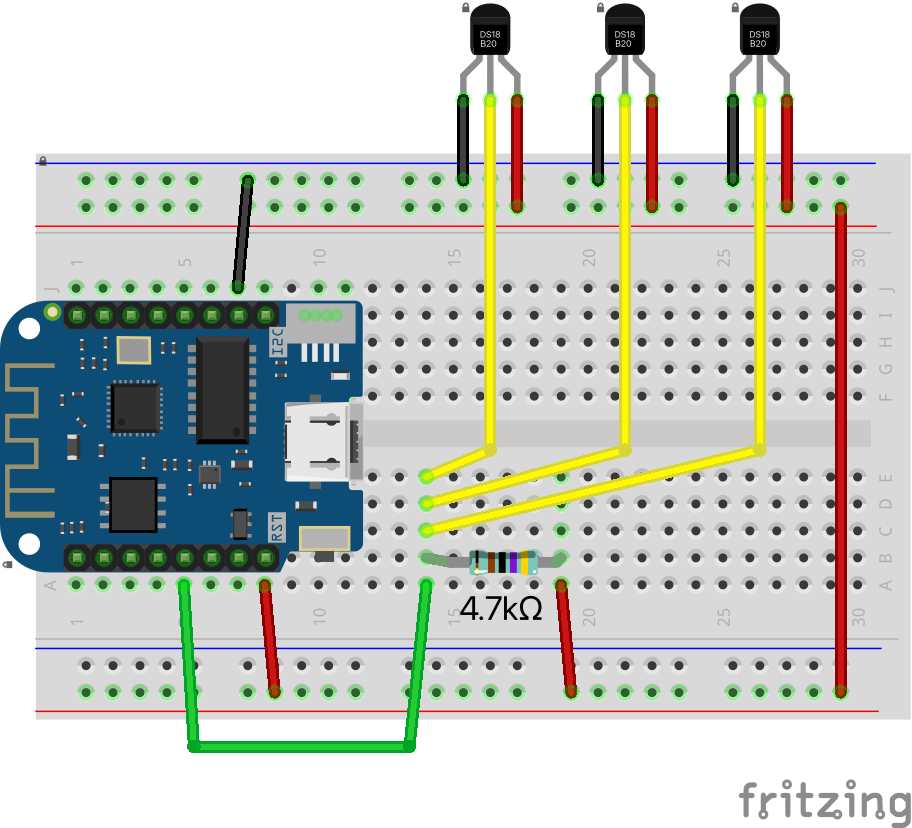
How to connect the DS18B20
Connecting the digital temperature sensor DS18B20 to an ESP-node or similar micro controller is really simple. In fact several DS18B20 sensors can share the same digital input of the node when connected in parallel.
Connect the red sensor wire to supply voltage 3.3 V, the black to GND, and the yellow data wire to one of the digital inputs on the ESP-node. Other wire color combinations do exist but this does not change the connection principle.
Put a resistor of 4.7k ohm between the data wire and the supply voltage in order to achieve a stable data transfer.
Operating the DS18B20 with a supply voltage of 5.0 V is also possible if the digital input of the micro controller requires this voltage.
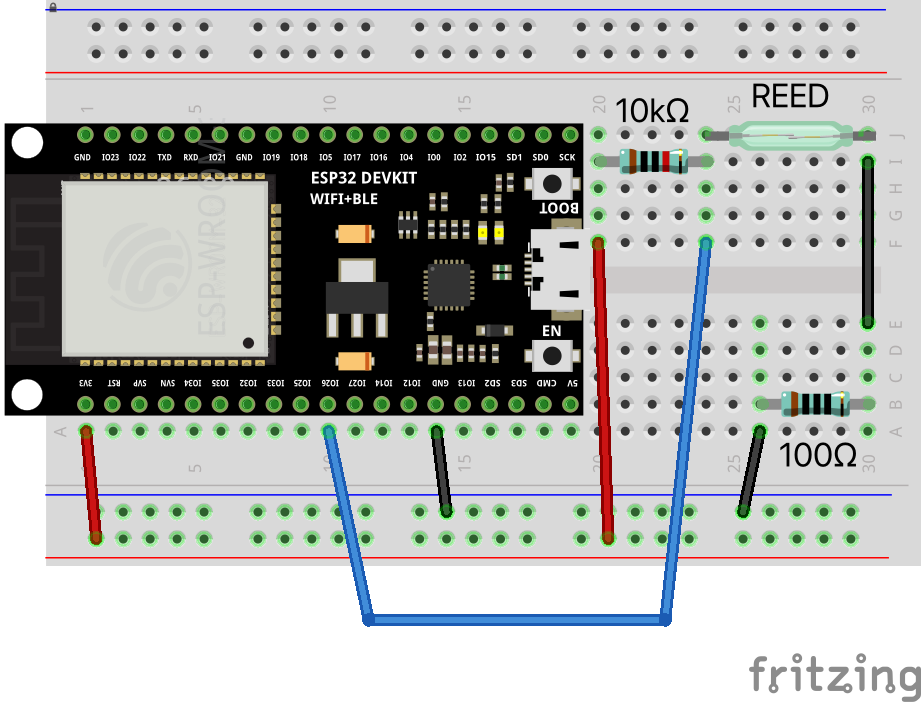
How to connect a reed switch
Connecting the reed switch to an ESP-node or similar micro controller is as easy as connecting an ordinary switch. Each reed switch is connected to a separate digital input of the node.
The reed switch has nearly no resistance when activated by a magnet (closed). Add a 100 ohm resistor before the input to prevent damage to the ESP-node if a short circuit is created by mistake.
To prevent the digital input on the ESP-node to become floating or undefined, connect a 10k ohm resistor between the input and the supply voltage (pull-up ![]() ).
).
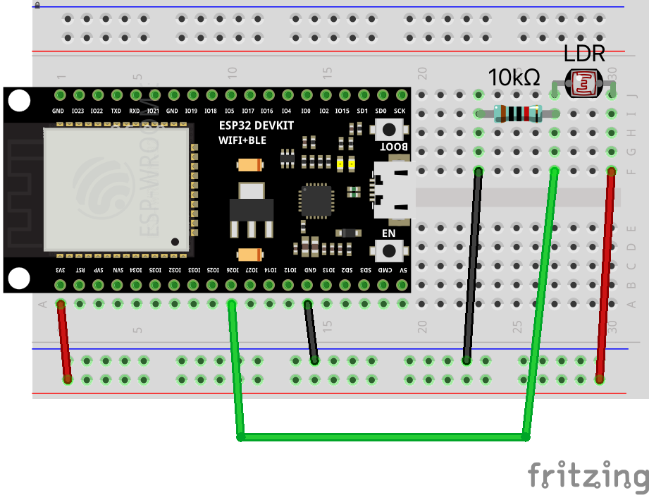
How to connect an LDR
Connecting the light intensity sensor LDR to an ESP-node or similar micro controller is very straight forward. Each LDR is connected to a separate digital input of the node.
To prevent the digital input on the ESP-node to become floating or undefined, connect a 10k ohm resistor between the input and ground (pull-down ![]() ).
).